The Envelope Follower is a plugin that analyzes an incoming audio signal and produces MIDI CC messages with values proportional to the magnitude of that signal.
Note: this feature is available in Gig Performer Pro.
Uses for electric guitar are, for example, signal-dependent Wah-wah or signal-dependent high cut-off filtering, which would produce almost violin-like effects. Another valuable use is for ducking audio while one is speaking. Read this blog article to see examples.
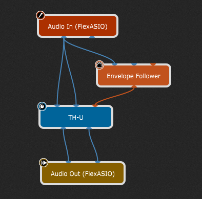
The produced MIDI CC messages are sent out through the MIDI output pin of the plugin, which needs to be connected to the MIDI input pin of another plugin, such as an effect plugin.
You can, for example, add an equalizer plugin and let the MIDI CC values control the central frequency of a bandpass filter to create a Wah-wah-like effect.
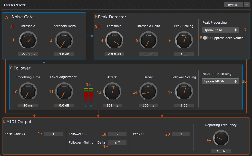
Double-clicking the Envelope Follower block opens its plugin editor window.
Features:
| • | A Noise Gate (A) to prevent processing of signals below a certain magnitude. Opening and closing of the gate is reported using MIDI CC messages. |
| • | A Peak Detector (B) to detect if the signals rise above a certain threshold. The results depend on the processing type and are reported using MIDI CC messages. |
| • | The envelope follower main controls (C). This component continuously reports the magnitude of the incoming signals. The rising and falling speed of the reported values are independently configurable. |
| • | An option to have an incoming MIDI CC value 'augmented' by the Envelope Follower output (D). |
| • | The MIDI CC numbers are configurable for all three components: Noise Gate, Peak Detector and Follower. |
| • | Outgoing MIDI messages always use channel 1 for the left audio signal and channel 2 for the right audio signal. This applies to all three components. |
| • | The MIDI CC number of the incoming MIDI messages (if used) must be the same as the MIDI CC number used by the follower. MIDI channel 1 is applied to the output of the left channel and MIDI channel 2 is applied to the output of the right channel. All other messages are discarded. |
Signal path
The signal path through this plugin is described in the following diagram:
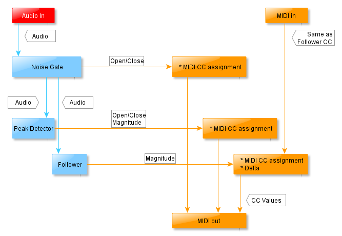
The first stage of the plugin is the Noise Gate (A). You can set the threshold at which the gate opens and the amount by which the signal has to drop below this threshold to close the gate. The noise gate processes the left and right channels in a 'linked' fashion: If one of the channels crosses the threshold, the gate opens for both channels. The gate stays open for both channels until both channels drop below the threshold (minus a delta). This delta makes sure that, when the signal level is just about equal to the threshold, the noise gate really opens or closes instead of going back and forth between those two states (flapping). Please note that the MIDI CC messages for the noise gate are sent for both audio channels (they always come in pairs).
The next stages are the Peak Detector (B) and the Follower (C). These two stages act independently of each other.
The Peak Detector takes the audio signal, and determines if it is above the Threshold (4) or drops below the threshold minus the Threshold Delta. The Peak Processing Control controls the output of the Peak Detector.
The signal of both channels is processed independently.
Except for the Open/Close Peak Processing mode, it is possible to suppress the reporting of CC values of zero, when the peak detector closes.
The Follower is the main part of the plugin. The audio signals are analyzed in the following way: First the audio signal is averaged to get rid of very fast fluctuations. The resulting magnitude is then processed by the attack/decay filters. This allows you to have the follower output react either quickly or slowly to audio signal attacks and/or decays. For example, if you set the attack slope to 2,000 ms, it will take 2 seconds to go from 0 to 127 in the output (if the input after gain is near 0 dB). When you use a guitar, you will notice that you will have to play rather loudly for quite some time. However, if you set both the attack and decay to 40 ms, the output will go from 0 to 127 on almost every stroke.
The blue arrows indicate the audio signal path, while the MIDI CC messages follow the orange arrows. The MIDI CC messages for the left audio channel are always reported on MIDI channel 1 and for the right audio channel on MIDI channel 2.
The last stage is MIDI Output (D). Here the MIDI CC numbers for the three components can be configured, as well as the frequency at which changes are reported and one special option for the follower (minimum delta).
Controls and indicators
The plugin has the following controls and indicators:
Noise Gate
| • | Threshold (1). This sets the audio signal level at which the gate should open. The noise gate evaluates the signal level of both audio channels and if one or more of the signals of the audio channels exceeds the threshold, both channels are opened. |
| • | Threshold Delta (2). This sets the amount the audio signal of both channels must drop below the threshold to close the gate. So, when the threshold is set at -60 dB, and the hysteresis is at 5 dB, the level of both audio channels must fall below -65 dB before the gate closes. |
| • | Indicator (3) reports whether the gate has opened (bright red) or not (dark red). |
Peak Detector
| • | Threshold (4). This sets the audio signal level at which a peak message will be reported. The peak detector independently evaluates the signal level of the audio channels and reports for each audio channel when the signal exceeds the threshold. |
| • | Threshold Delta (5). This sets the amount of audio signal that both channels must drop below the threshold to report a 'no peak' message. So, when the threshold is set at -12 dB and the hysteresis is at 5 dB, the level of an audio channel must fall below -17 dB before processing stops for a particular channel (possibly also sending a MIDI CC value, depending on the Suppress zero values (8) discussed below). |
| • | Peak Scaling (6). This sets the value by which the MIDI CC values are multiplied. It allows the user to increase or decrease the outputted CC values. For example, when this control is set to 0.5 and internally the determined value is 150 (which is higher than the allowed maximum value of 127 for MIDI CC values), the outputted value becomes 150 * 1.5 -> 75. If this control had been set to 1.0, the outputted value would have been 127, because the plugin keeps the CC values within the allowed range of 0 .. 127. Note that the calculation takes place before the minimum value (0) and maximum value (127) is applied |
| • | Peak Processing (7). This control determines what kind of output is sent. Roughly this output falls into two categories: Simple On/Off (127/0) or the magnitude: |
| - Open/Close: The output is 127 if the channel input is greater than the threshold or 0 if it drops below the threshold minus delta. |
| - Oneshot: The output is the magnitude of the audio signal (mapped to a range of 0 – 127) multiplied by the Peak Scaling factor (6). This only occurs once until the signal drops below the threshold minus delta. Then it will be ‘rearmed’. |
| - Continuous: The output is the magnitude of the audio signal (mapped to a range of 0 – 127) multiplied by the Peak Scaling factor (6). All magnitude changes will be sent, until the signal drops below the threshold minus delta. |
| - Continuous Rising: The output is the magnitude of the audio signal (mapped to a range of 0 – 127) multiplied by the Peak Scaling factor (6). Magnitudes greater than the previously reported magnitude will be sent until the signal drops below the threshold minus delta. |
| • | Suppress Zero Values (8). This control simply prevents the peak detector from sending MIDI CC values of 0 when the magnitude of the input signal falls below the threshold minus delta. Suppressing zeros is not available for the Open/Close processing mode. |
| • | Indicator (9) reports whether a peak level is currently being detected for one or more audio channels (bright red) or not (dark red). |
| • | Indicators (22) report the current output values. |
Follower
| • | Smoothing Time (10). This sets the size of the window of the first stage of the follower. Please note that the size of this window adds latency to the speed at which the follower responds to attack and decay slopes of the follower MIDI CC messages. Most of the time 20 ms will do nicely. |
| • | Level Adjustment (11). This control increases the level of the signal after the averaging filter before entering the attack and decay filters. You should adjust the gain to have the Level Indicators (12) reach the green level. This way the timings provided by the attack and decay controls are more accurate. Yellow means the level is set too high, red means the level is set too low. |
| • | The next two plugin controls are the attack and decay slope controls. These are the most important controls, because they determine by large the character of the eventually resulting sound, for example a Wah-wah-like effect using an attack and decay somewhere between 40 to 200 ms combined with a steep band-pass filter or a signal-dependent VCF effect using longer times (> 500 ms) combined with a low-pass filter. The timings indicated by these controls are just that: indications. The true timings are strongly dependent on the actual audio input signal levels. These settings depend a lot on the type of audio signal: percussive sounds might benefit from shorter times, while padding-like sounds can be used with longer times. Ultimately, your ears will decide what works best for the effect you want to accomplish. |
| - Attack (13). This control sets the speed in milliseconds at which the value of the MIDI CC messages produced by the follower should increase from 0 to 127. For example, when this control is set to 1,500 ms and the gain is adjusted the right way, when the input signal level is about 0 dB it will take 1.5 seconds to have the value of the outputted MIDI messages go from 0 to 127 (provided that this value is 0 at the start of the measurement). |
| - Decay (14). This control sets the speed in milliseconds at which the value of the MIDI CC messages produced by the follower should drop from 127 to 0. For example, when this control is set to 3,000 ms and the gain is adjusted the right way, when the input signal level is about infinite dB it will take 3.0 seconds to have the value of the outputted MIDI messages drop from 127 to 0 (provided that this value is 127 at the start of the measurement). |
| • | Follower Scaling (15). This sets the value by which the MIDI CC values are multiplied. It allows the user to increase or decrease the outputted CC values. For example, when this control is set to 0.5 and internally the determined value is 150 (which is above the allowed maximum of 127 for MIDI CC values), the output value becomes 150 * 1.5 -> 75. If this control had been set to 1.0, the output value would have been 127, because the plugin keeps the CC values within the allowed range of 0 .. 127. Note that the calculation takes place before the minimum value (0) and maximum value (127) are applied. |
| • | MIDI-In processing (16). This control allows you to have an incoming MIDI CC value added to the output. |
Only incoming MIDI messages with a CC number that is the same as that of the follower (see MIDI output below for more details) are processed.
MIDI channel 1 values apply to the left audio channel, whereas MIDI channel 2 values apply to the right audio channel.
| There are three types of processing: |
| - Ignore MIDI-in. The incoming MIDI CC messages are ignored. |
| - Adding 0..127. This adds the incoming MIDI CC value to the output after applying the Follower Scaling. |
| - Adding -64..0..63. The incoming MIDI CC values in the range of 0..127 are translated to -64..63. So, an incoming MIDI CC value of 0 results in subtracting -64 of the output and 127 actually adds 63. A MIDI CC value of 64 does not add or subtract anything. |
| • | Indicators (23) report the current output values. |
MIDI Output
| • | The next three controls determine the MIDI CC number that is used for the various parts of the plugin. As said before, the MIDI channel of the messages always depends on the audio channel: MIDI channel 1 represents the left audio channel, whereas MIDI channel 2 represents the right audio channel. You can assign the same CC number to all messages, but then there is no way to distinguish the messages of the three components, so it is strongly advised that you don't do that. |
| - Noise Gate CC (17). Sets the CC number of the noise gate reports. |
| - Follower CC (18). Sets the CC number of the follower reports. |
| - Peak CC (20). Sets the CC number of the peak detector reports. |
| Setting a value to 'Off' causes no reports to be sent for that particular component (Noise Gate/Follower/Peak Detector). |
| • | Follower Minimum Delta (19). Setting this value to 2 or higher sets the interval of the MIDI CC values of the follower part. For example, if the most recently outputted MIDI CC value is 12 and this control is set to 4, then the MIDI CC value has to rise to 16 or higher or drop to 8 or lower, before a new report is emitted. |
| Setting the value to 'Off' causes the normal behavior: All changes are reported. |
| • | Reporting Frequency (21). This control sets the number of times per second the plugin should check for changes to report. Note that there will only be a report of this change if there is a change to a particular MIDI CC value. If the rate is set very low (for example, 2 checks per second), the output will become rather coarse with large jumps. Higher settings result in a much smoother response. Typically, somewhere between 15 – 30 will do nicely, but you can crank it up to 50 checks per second. |
How to use an Envelope Follower
Here is an example of how to use this plugin:
| 1. | Add the Envelope Follower plugin and route the input signal from an electric guitar (say) to the plugin's left audio input. |
| 2. | Add an equalizer plugin (for example, the MEqualizer plugin from MeldaProduction). |
| 3. | Route the MIDI output of the Envelope Follower plugin to the MIDI input of the equalizer plugin. |
| 4. | Modify the equalizer so that MIDI CC number 7 controls the central frequency of a band pass filter. |
| 5. | Connect the equalizer plugin somewhere between the signal inputs and signal outputs. |
| 6. | Play the instrument and adjust the Level Adjustment (11) of the plugin. If the level indicator (12) reaches the green level (second ‘led’ from the top) rather often, then the applied gain is right. |
| 7. | Adjust the attack (13) and decay (14) controls to your liking. |
| 8. | Have fun. |
To see examples of how to use this plugin, check out our blog and this community thread.
Notes
| • | You can resize the plugin editor window by grabbing and dragging the lower-right corner. |
| • | The values of the controls can also be directly modified by clicking on the value. |
| • | The controls without a knob can also be modified by dragging the mouse in the value box. You can slow down the speed at which values change by pressing the Ctrl key (or the Cmd key on a Mac) while you drag the mouse. |
Envelope Follower parameters
The following parameters are available for the Envelope follower plugin:
•Reporting Frequency - adjusts the reporting frequency in the MIDI Output section, from 1 Hz to 50 Hz.
•Follower Level Adjustment - adjusts the level adjustment in the Follower section, 0 dB to 30 dB.
•Follower Attack - adjusts the attack in the Follower section, from 10 ms to 3000 ms.
•Follower Decay - adjusts the decay in the Follower section, from 10 ms to 3000 ms.
•Follower Smoothing Time - adjusts the smoothing time in the Follower section, from 20 ms to 100 ms.
•Follower Scaling - adjusts the follower scaling in the Follower section, from 0.10 to 3.00.
•MIDI-In processing - sets the type of the MIDI-In processing: Ignore MIDI-in, Adding 0..127, or Adding -64..0..63.
•Peak Threshold - adjusts the threshold in the Peak Detector section, from -100 dB to 12 dB.
•Peak Threshold Delta - adjusts the threshold delta in the Peak Detector section, from 3 dB to 30 dB.
•Suppress Peak Off Reports - controls the Suppress Zero Values toggle button in the Peak Detector section (Off/On).
•Peak Detector Scaling - adjusts the peak scaling in the Peak Detector section, from 0.10 to 3.00.
•Peak Processing - sets the type of the Peak Processing: Open/Close, Oneshot, Continuous, Continuous Rising.
•Noise Gate Threshold - adjusts the threshold in the Noise Gate section, from -100 dB to 0 dB.
•Noise Gate Threshold Delta - adjusts the threshold delta in the Noise Gate section, from 3 dB to 30 dB.
•Noise Gate CC - adjusts the noise gate CC value in the MIDI Output section, from Off to 127.
•Peak Detector CC - adjusts the Peak CC value in the MIDI Output section, from Off to 127.
•Follower CC - adjusts the follower CC value in the MIDI Output section, from Off to 127.
•Follower Minimum Delta - adjusts the follower minimum delta value in the MIDI Output section, from Off to 127.
•Audio Level Channel 0 - shows the incoming audio level, channel 0.
•Audio Level Channel 1 - shows the incoming audio level, channel 1.
•Follower Level Channel 0 - shows the incoming audio level altered by the Follower section, channel 0.
•Follower Level Channel 1 - shows the incoming audio level altered by the Follower section, channel 1.
•Peak State Overall - shows the Threshold led in the Peak Detector section (Off/On).
•Peak Level Channel 0 - shows the incoming audio level altered by the Peak Detector section, channel 0.
•Peak Level Channel 1 - shows the incoming audio level altered by the Peak Detector section, channel 1.
•Noise Gate State - shows the state of the noise gate (Closed/Open).